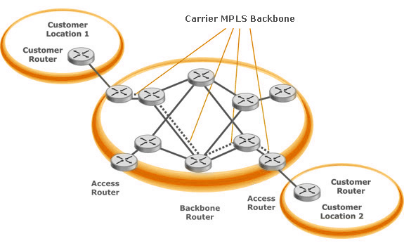
Voici la suite du tutoriel entamé précédemment. Je remets la topologie pour plus de facilité ;-).

Pour rappel, nous avons déjà configuré le routage interne de l’opérateur, activé le MPLS et configuré les VRF des clients sur les routeurs en périphérie (les PE). Cependant, nous n’avons pas encore touché aux CPE des clients (les routeurs C1-S0, C1-S1, etc.). Nous allons donc remédier à cela :).
Configuration des équipements clients
Nous allons d’abord configurer la connectivité IP puis du NAT sur chacun des routeurs clients.
Routeur C1-S0 :
interface Ethernet0/0
 description *** VERS PE1 - 130.12.40.2/30 ***
 ip address 130.12.40.1 255.255.255.252
 ip nat outside
!
interface Ethernet0/1
 description *** COLLECTE RESEAU - 192.168.0.0/24 ***
 ip address 192.168.0.254 255.255.255.0
 ip nat inside
!
ip access-list extended ACL-NAT-CLIENT-001
 deny ip 192.168.0.0 0.0.255.255 192.168.0.0 0.0.255.255
 permit ip 192.168.0.0 0.0.0.255 any
!
ip nat inside source list ACL-NAT-CLIENT-001 interface Ethernet0/0 overload
Routeur C1-S1 :
interface Ethernet0/0
 description *** VERS PE2 - 130.12.41.2/30 ***
 ip address 130.12.41.1 255.255.255.252
 ip nat outside
!
interface Ethernet0/1
 description *** COLLECTE RESEAU - 192.168.1.0/24 ***
 ip address 192.168.1.254 255.255.255.0
 ip nat inside
!
ip access-list extended ACL-NAT-CLIENT-001
 deny ip 192.168.0.0 0.0.255.255 192.168.0.0 0.0.255.255
 permit ip 192.168.1.0 0.0.0.255 any
!
ip nat inside source list ACL-NAT-CLIENT-001 interface Ethernet0/0 overload
Routeur C1-S2 :
interface Ethernet0/0
 description *** VERS PE3 - 130.12.42.2/30 ***
 ip address 130.12.42.1 255.255.255.252
 ip nat outside
!
interface Ethernet0/1
 description *** COLLECTE RESEAU - 192.168.2.0/24 ***
 ip address 192.168.2.254 255.255.255.0
 ip nat inside
!
ip access-list extended ACL-NAT-CLIENT-001
 deny ip 192.168.0.0 0.0.255.255 192.168.0.0 0.0.255.255
 permit ip 192.168.2.0 0.0.0.255 any
!
ip nat inside source list ACL-NAT-CLIENT-001 interface Ethernet0/0 overload
Routeur C2-S0 :
interface Ethernet0/0
 description *** VERS PE1 - 140.12.40.2/30 ***
 ip address 140.12.40.1 255.255.255.252
 ip nat outside
!
interface Ethernet0/1
 description *** COLLECTE RESEAU - 172.16.0.0/24 ***
 ip address 172.16.0.254 255.255.255.0
 ip nat inside
!
ip access-list extended ACL-NAT-CLIENT-002
 deny ip 172.16.0.0 0.0.255.255 172.16.0.0 0.0.255.255
 permit ip 172.16.0.0 0.0.0.255 any
!
ip nat inside source list ACL-NAT-CLIENT-002 interface Ethernet0/0 overload
Routeur C2-S1 :
interface Ethernet0/0
 description *** VERS PE2 - 140.12.41.2/30 ***
 ip address 140.12.41.1 255.255.255.252
 ip nat outside
!
interface Ethernet0/1
 description *** COLLECTE RESEAU - 172.16.1.0/24 ***
 ip address 172.16.1.254 255.255.255.0
 ip nat inside
!
ip access-list extended ACL-NAT-CLIENT-002
 deny ip 172.16.0.0 0.0.255.255 172.16.0.0 0.0.255.255
 permit ip 172.16.1.0 0.0.0.255 any
!
ip nat inside source list ACL-NAT-CLIENT-002 interface Ethernet0/0 overload
Routeur C2-S2 :
interface Ethernet0/0
 description *** VERS PE3 - 140.12.42.2/30 ***
 ip address 140.12.42.1 255.255.255.252
 ip nat outside
!
interface Ethernet0/1
 description *** COLLECTE RESEAU - 172.16.2.0/24 ***
 ip address 172.16.2.254 255.255.255.0
 ip nat inside
!
ip access-list extended ACL-NAT-CLIENT-002
 deny ip 172.16.0.0 0.0.255.255 172.16.0.0 0.0.255.255
 permit ip 172.16.2.0 0.0.0.255 any
!
ip nat inside source list ACL-NAT-CLIENT-002 interface Ethernet0/0 overload
Il ne restera plus qu’à configurer un protocole de routage et tout ce petit monde pourra communiquer ensemble (client 1 à client 1 et client 2 à client 2 évidemment).
Configuration du BGP
Mais avant de pouvoir faire cela nous devons mettre en place du protocole de routage BGP sur le réseau opérateur afin que les différents routeurs puissent s’échanger leurs routes puis, plus tard dans ce tutoriel, pour que le réseau opérateur puisse s’interconnecter à Internet afin d’annoncer ses clients.
BGP, étant un protocole d’échange de routes, va nous permettre d’échanger les informations entre les différents sites clients par le biais des VRF (et notamment des routes-target). Le numéro d’AS accordé à l’opérateur sera 1200.
Routeur P1 :
router bgp 1200
 bgp log-neighbor-changes
 neighbor 10.100.0.1 remote-as 1200
 neighbor 10.100.0.1 update-source Loopback0
 neighbor 10.100.0.2 remote-as 1200
 neighbor 10.100.0.2 update-source Loopback0
 neighbor 10.100.0.3 remote-as 1200
 neighbor 10.100.0.3 update-source Loopback0
 neighbor 10.100.0.253 remote-as 1200
 neighbor 10.100.0.253 update-source Loopback0
 !
 address-family ipv4
 neighbor 10.100.0.1 activate
 neighbor 10.100.0.2 activate
 neighbor 10.100.0.3 activate
 neighbor 10.100.0.253 activate
 no auto-summary
 exit-address-family
Routeur P2 :
router bgp 1200
 bgp log-neighbor-changes
 neighbor 10.100.0.1 remote-as 1200
 neighbor 10.100.0.1 update-source Loopback0
 neighbor 10.100.0.2 remote-as 1200
 neighbor 10.100.0.2 update-source Loopback0
 neighbor 10.100.0.3 remote-as 1200
 neighbor 10.100.0.3 update-source Loopback0
 neighbor 10.100.0.254 remote-as 1200
 neighbor 10.100.0.254 update-source Loopback0
 !
 address-family ipv4
 no synchronization
 neighbor 10.100.0.1 activate
 neighbor 10.100.0.2 activate
 neighbor 10.100.0.3 activate
 neighbor 10.100.0.254 activate
 no auto-summary
 exit-address-family
Routeur PE1 :
router bgp 1200
 bgp log-neighbor-changes
 neighbor 10.100.0.2 remote-as 1200
 neighbor 10.100.0.2 update-source Loopback0
 neighbor 10.100.0.3 remote-as 1200
 neighbor 10.100.0.3 update-source Loopback0
 neighbor 10.100.0.253 remote-as 1200
 neighbor 10.100.0.253 update-source Loopback0
 neighbor 10.100.0.254 remote-as 1200
 neighbor 10.100.0.254 update-source Loopback0
 !
 address-family ipv4
 no synchronization
 neighbor 10.100.0.2 activate
 neighbor 10.100.0.3 activate
 neighbor 10.100.0.253 activate
 neighbor 10.100.0.254 activate
 no auto-summary
 exit-address-family
Routeur PE2 :
router bgp 1200
 bgp log-neighbor-changes
 neighbor 10.100.0.1 remote-as 1200
 neighbor 10.100.0.1 update-source Loopback0
 neighbor 10.100.0.3 remote-as 1200
 neighbor 10.100.0.3 update-source Loopback0
 neighbor 10.100.0.253 remote-as 1200
 neighbor 10.100.0.253 update-source Loopback0
 neighbor 10.100.0.254 remote-as 1200
 neighbor 10.100.0.254 update-source Loopback0
 !
 address-family ipv4
 no synchronization
 neighbor 10.100.0.1 activate
 neighbor 10.100.0.3 activate
 neighbor 10.100.0.253 activate
 neighbor 10.100.0.254 activate
 no auto-summary
 exit-address-family
Routeur PE3 :
router bgp 1200
 bgp log-neighbor-changes
 neighbor 10.100.0.1 remote-as 1200
 neighbor 10.100.0.1 update-source Loopback0
 neighbor 10.100.0.2 remote-as 1200
 neighbor 10.100.0.2 update-source Loopback0
 neighbor 10.100.0.253 remote-as 1200
 neighbor 10.100.0.253 update-source Loopback0
 neighbor 10.100.0.254 remote-as 1200
 neighbor 10.100.0.254 update-source Loopback0
 !
 address-family ipv4
 no synchronization
 neighbor 10.100.0.1 activate
 neighbor 10.100.0.2 activate
 neighbor 10.100.0.253 activate
 neighbor 10.100.0.254 activate
 no auto-summary
 exit-address-family
Le BGP est à présent opérationnel, il ne reste plus qu’à s’occuper du routage client.
Configuration de l’OSPF client
Vous l’aurez compris, je compte utiliser le protocole de routage OSPF pour les routes clientes. Cependant, un problème se heurte à moi : chaque client aura un processus OSPF dédié mais c’est bel et bien BGP qui va me permettre d’échanger les routes entre les routeurs opérateur. Alors comment allier les deux ? Et bien, il va me suffire de redistribuer les routes BGP dans mon processus OSPF et vice-versa. Et comme nous avons isolé les clients dans des VRF, tout sera bien organisé. Magique non ? ;-).
Rappel sur la configuration des clients :
| ID Routeur | VRF | route-target | Adresse IP | LAN | |
| Client 1 | C1-S0 | CLIENT-001 | 10:0 | 130.12.40.1 | 192.168.0.0/24 |
| C1-S1 | CLIENT-001 | 10:1 | 130.12.41.1 | 192.168.1.0/24 | |
| C1-S2 | CLIENT-001 | 10:2 | 130.12.42.1 | 192.168.2.0/24 | |
| Client 2 | C2-S0 | CLIENT-002 | 20:0 | 140.12.40.1 | 172.16.0.0/24 |
| C2-S1 | CLIENT-002 | 20:1 | 140.12.41.1 | 172.16.1.0/24 | |
| C2-S2 | CLIENT-002 | 20:2 | 140.12.42.1 | 172.16.2.0/24 |
Routeur PE1 :
router ospf 10 vrf CLIENT-001
 router-id 130.12.40.2
 log-adjacency-changes
 redistribute bgp 1200 metric 1 subnets
 network 130.12.40.0 0.0.0.3 area 0
!
router ospf 20 vrf CLIENT-002
 router-id 140.12.40.2
 log-adjacency-changes
 redistribute bgp 1200 metric 1 subnets
 network 140.12.40.0 0.0.0.3 area 0
!
router bgp 1200
address-family vpnv4
 neighbor 10.100.0.2 activate
 neighbor 10.100.0.2 send-community both
 neighbor 10.100.0.3 activate
 neighbor 10.100.0.3 send-community both
 exit-address-family
 !
 address-family ipv4 vrf CLIENT-001
 no synchronization
 redistribute ospf 10 vrf CLIENT-001 metric 1
 exit-address-family
 !
 address-family ipv4 vrf CLIENT-002
 no synchronization
 redistribute ospf 20 vrf CLIENT-002 metric 1
 exit-address-family
Routeur PE2 :
router ospf 10 vrf CLIENT-001
 router-id 130.12.41.2
 log-adjacency-changes
 redistribute bgp 1200 metric 1 subnets
 network 130.12.41.0 0.0.0.3 area 0
!
router ospf 20 vrf CLIENT-002
 router-id 140.12.41.2
 log-adjacency-changes
 redistribute bgp 1200 metric 1 subnets
 network 140.12.41.0 0.0.0.3 area 0
!
router bgp 1200
address-family vpnv4
 neighbor 10.100.0.1 activate
 neighbor 10.100.0.1 send-community both
 neighbor 10.100.0.3 activate
 neighbor 10.100.0.3 send-community both
 exit-address-family
 !
 address-family ipv4 vrf CLIENT-001
 no synchronization
 redistribute ospf 10 vrf CLIENT-001 metric 1
 exit-address-family
 !
 address-family ipv4 vrf CLIENT-002
 no synchronization
 redistribute ospf 20 vrf CLIENT-002 metric 1
 exit-address-family
Routeur PE3 :
router ospf 10 vrf CLIENT-001
 router-id 130.12.42.2
 log-adjacency-changes
 redistribute bgp 1200 metric 1 subnets
 network 130.12.42.0 0.0.0.3 area 0
!
router ospf 20 vrf CLIENT-002
 router-id 140.12.42.2
 log-adjacency-changes
 redistribute bgp 1200 metric 1 subnets
 network 140.12.42.0 0.0.0.3 area 0
!
router bgp 1200
address-family vpnv4
 neighbor 10.100.0.1 activate
 neighbor 10.100.0.1 send-community both
 neighbor 10.100.0.2 activate
 neighbor 10.100.0.2 send-community both
 exit-address-family
 !
 address-family ipv4 vrf CLIENT-001
 no synchronization
 redistribute ospf 10 vrf CLIENT-001 metric 1
 exit-address-family
 !
 address-family ipv4 vrf CLIENT-002
 no synchronization
 redistribute ospf 20 vrf CLIENT-002 metric 1
 exit-address-family
Configuration du routage sur les équipements clients
Mon routage client est configuré côté opérateur, il ne me reste plus qu’à déclarer les routes situés sur les sites clients (les LAN).
Routeur C1-S0 :
router ospf 10
 router-id 130.12.40.1
 log-adjacency-changes
 network 130.12.40.0 0.0.0.3 area 0
 network 192.168.0.0 0.0.0.255 area 0
!
ip route 0.0.0.0 0.0.0.0 130.12.40.2
Routeur C1-S1 :
router ospf 10
 router-id 130.12.41.1
 log-adjacency-changes
 network 130.12.41.0 0.0.0.3 area 0
 network 192.168.1.0 0.0.0.255 area 0
!
ip route 0.0.0.0 0.0.0.0 130.12.41.2
Routeur C1-S2 :
router ospf 10
 router-id 130.12.42.1
 log-adjacency-changes
 network 130.12.42.0 0.0.0.3 area 0
 network 192.168.2.0 0.0.0.255 area 0
!
ip route 0.0.0.0 0.0.0.0 130.12.42.2
Routeur C2-S0 :
router ospf 20
 router-id 140.12.40.1
 log-adjacency-changes
 network 140.12.40.0 0.0.0.3 area 0
 network 172.16.0.0 0.0.0.255 area 0
!
ip route 0.0.0.0 0.0.0.0 140.12.40.2
Routeur C2-S1 :
router ospf 20
 router-id 140.12.41.1
 log-adjacency-changes
 network 140.12.41.0 0.0.0.3 area 0
 network 172.16.1.0 0.0.0.255 area 0
!
ip route 0.0.0.0 0.0.0.0 140.12.41.2
Routeur C2-S2 :
router ospf 20
 router-id 140.12.42.1
 log-adjacency-changes
 network 140.12.42.0 0.0.0.3 area 0
 network 172.16.2.0 0.0.0.255 area 0
!
ip route 0.0.0.0 0.0.0.0 140.12.42.2
Vérifications :
Normalement, si vous avez bien suivit toutes les consignes, vous devriez avoir un routage parfait entre les différents sites de vos clients. Voici à quoi doit ressembler les tables de routage :
C1-S0#show ip route
Codes: L - local, C - connected, S - static, R - RIP, M - mobile, B - BGP
 D - EIGRP, EX - EIGRP external, O - OSPF, IA - OSPF inter area
 N1 - OSPF NSSA external type 1, N2 - OSPF NSSA external type 2
 E1 - OSPF external type 1, E2 - OSPF external type 2
 i - IS-IS, su - IS-IS summary, L1 - IS-IS level-1, L2 - IS-IS level-2
 ia - IS-IS inter area, * - candidate default, U - per-user static route
 o - ODR, P - periodic downloaded static route, + - replicated route

Gateway of last resort is 130.12.40.2 to network 0.0.0.0

S* 0.0.0.0/0 [1/0] via 130.12.40.2
 130.12.0.0/16 is variably subnetted, 4 subnets, 2 masks
C 130.12.40.0/30 is directly connected, Ethernet0/0
L 130.12.40.1/32 is directly connected, Ethernet0/0
O IA 130.12.41.0/30 [110/11] via 130.12.40.2, 00:50:14, Ethernet0/0
O IA 130.12.42.0/30 [110/11] via 130.12.40.2, 00:50:14, Ethernet0/0
 192.168.0.0/24 is variably subnetted, 2 subnets, 2 masks
C 192.168.0.0/24 is directly connected, Ethernet0/1
L 192.168.0.254/32 is directly connected, Ethernet0/1
O IA 192.168.1.0/24 [110/11] via 130.12.40.2, 00:49:07, Ethernet0/0
O IA 192.168.2.0/24 [110/11] via 130.12.40.2, 00:47:16, Ethernet0/0
C2-S0#show ip route
Codes: L - local, C - connected, S - static, R - RIP, M - mobile, B - BGP
 D - EIGRP, EX - EIGRP external, O - OSPF, IA - OSPF inter area
 N1 - OSPF NSSA external type 1, N2 - OSPF NSSA external type 2
 E1 - OSPF external type 1, E2 - OSPF external type 2
 i - IS-IS, su - IS-IS summary, L1 - IS-IS level-1, L2 - IS-IS level-2
 ia - IS-IS inter area, * - candidate default, U - per-user static route
 o - ODR, P - periodic downloaded static route, + - replicated route

Gateway of last resort is 140.12.40.2 to network 0.0.0.0

S* 0.0.0.0/0 [1/0] via 140.12.40.2
 140.12.0.0/16 is variably subnetted, 4 subnets, 2 masks
C 140.12.40.0/30 is directly connected, Ethernet0/0
L 140.12.40.1/32 is directly connected, Ethernet0/0
O IA 140.12.41.0/30 [110/11] via 140.12.40.2, 00:46:30, Ethernet0/0
O IA 140.12.42.0/30 [110/11] via 140.12.40.2, 00:46:30, Ethernet0/0
 172.16.0.0/16 is variably subnetted, 4 subnets, 2 masks
C 172.16.0.0/24 is directly connected, Ethernet0/1
L 172.16.0.254/32 is directly connected, Ethernet0/1
O IA 172.16.1.0/24 [110/11] via 140.12.40.2, 00:44:44, Ethernet0/0
O IA 172.16.2.0/24 [110/11] via 140.12.40.2, 00:43:20, Ethernet0/0
A présent vos clients peuvent communiquer avec l’ensemble de leurs sites distants. La prochaine étape (dans le prochain tutoriel) sera de configurer une connectivité à Internet par le biais du routeur PEERING.